TI Tiva C Series TM4C129E Crypto Connected LaunchPad
Overview
The EK-TM4C129EXL Crypto Connected LaunchPad is an evaluation board for the TI TM4C129ENCPDT microcontroller. It has an ARM Cortex-M4F core running at up to 120 MHz, 1 MB of flash, and 256 KB of SRAM.
The TM4C129ENCPDT microcontroller includes:
Core.
ARM Cortex-M4F with FPU, up to 120 MHz.
Nested Vectored Interrupt Controller (NVIC).
Memory Protection Unit (MPU).
Memory.
1 MB flash.
256 KB SRAM.
6 KB EEPROM.
Communication.
Eight UARTs.
Four QSSI/QSPI modules.
Ten I2C modules.
Two CAN 2.0 A/B controllers.
USB 2.0 OTG/Host/Device. High-speed operation requires an external USB PHY.
Integrated 10/100 Ethernet MAC and PHY.
Timers.
Eight 16/32-bit general-purpose timer blocks.
Two watchdog timers.
Eight PWM outputs.
One quadrature encoder interface (QEI) module.
Analog.
Two 12-bit ADC modules.
Other.
Hardware cryptography accelerators.
A 32-channel uDMA controller.
A hibernation module.
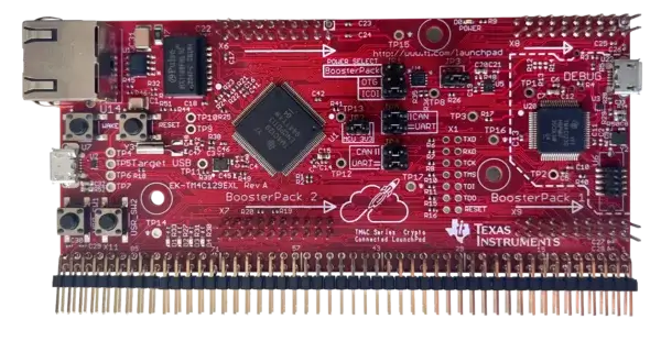
Hardware
The EK-TM4C129EXL features:
On-board In-Circuit Debug Interface (ICDI) for programming and debugging
Two user switches: SW1 on PJ0, SW2 on PJ1.
Four user LEDs: D1 on PN1, D2 on PN0, D3 on PF4, and D4 on PF0. D3 and D4 are shared with the Ethernet peripheral.
Reset and wake switches.
10/100 Ethernet connector.
A debug USB Micro-B connector for the ICDI and board power.
A target USB Micro-A/B connector for the microcontroller’s USB interface. It can also supply board power.
A JP1 jumper to select the board’s power source.
Two BoosterPack XL expansion sites.
See the TI EK-TM4C129EXL product page for board documentation.
Supported Features
The following Zephyr features are currently supported on the EK-TM4C129EXL:
The tm4c129exl board supports the hardware features listed below.
- on-chip / on-board
- Feature integrated in the SoC / present on the board.
- 2 / 2
-
Number of instances that are enabled / disabled.
Click on the label to see the first instance of this feature in the board/SoC DTS files. -
vnd,foo -
Compatible string for the Devicetree binding matching the feature.
Click on the link to view the binding documentation.
tm4c129exl/ti_tm4c129encpdt target
On-target memory for this board target: 256 KiB of RAM, 1 MiB of Flash.
Type |
Location |
Description |
Compatible |
|---|---|---|---|
CPU |
on-chip |
ARM Cortex-M4F CPU1 |
|
Clock control |
on-chip |
Generic fixed-rate clock provider1 |
|
Flash controller |
on-chip |
TI Stellaris flash controller1 |
|
Interrupt controller |
on-chip |
ARMv7-M NVIC (Nested Vectored Interrupt Controller)1 |
|
MTD |
on-chip |
Flash node1 |
|
Pin control |
on-chip |
TI Tiva C Series pin controller1 |
|
Serial controller |
on-chip |
||
SRAM |
on-chip |
Generic on-chip SRAM1 |
|
Timer |
on-chip |
ARMv7-M System Tick1 |
The TM4C129ENCPDT contains additional peripherals which are not yet enabled by the current Zephyr board support.
Connections and IOs
UART
The microcontroller has eight UART modules. With JP4 and JP5 in their default horizontal positions, UART0 is connected to the on-board ICDI virtual serial port. UART1 is available on the X11 breadboard expansion pads.
Moving JP4 and JP5 to the CAN-enabled vertical positions changes the ICDI virtual serial port connection from UART0 to UART2.
UART |
RX pin |
TX pin |
X11 RX pad |
X11 TX pad |
|---|---|---|---|---|
UART0 |
PA0 |
PA1 |
74 |
76 |
UART1 |
PB0 |
PB1 |
58 |
60 |
UART2 |
PD4 |
PD5 |
40 |
38 |
Building and Flashing
Building
Follow the Getting Started Guide instructions for Zephyr application development.
For example, to build the Hello World application for the EK-TM4C129EXL:
# From the root of the zephyr repository
west build -b tm4c129exl/ti_tm4c129encpdt samples/hello_world
Flashing
The EK-TM4C129EXL uses the on-board TI ICDI interface for flashing via OpenOCD.
# From the root of the zephyr repository
west build -b tm4c129exl/ti_tm4c129encpdt samples/hello_world
west flash
Debugging
The on-board ICDI provides a JTAG debug connection to the TM4C129ENCPDT. OpenOCD is used by the Zephyr board configuration for flashing and debugging.
Flashing through the ICDI using OpenOCD is supported. Debugging through
west debug has not yet been validated for this board configuration.
An external JTAG debug probe can also be connected through the board’s ARM 10-pin connector.
Console
With JP4 and JP5 in their default horizontal position, the UART0 console is available through the on-board ICDI virtual COM port. Connect to the serial port at 115200 8N1.
On Linux:
$ screen /dev/ttyACM0 115200