Sentrius BT510 Sensor
Overview
The Sentrius™ BT510 Sensor is a battery powered, Bluetooth v5 Long Range integrated sensor that uses a Nordic Semiconductor nRF52840 ARM Cortex-M4F CPU.
The sensor has the following features:
ADC
CLOCK
FLASH
GPIO
I2C
MPU
NVIC
PWM
RADIO (Bluetooth Low Energy and 802.15.4)
RTC
Segger RTT (RTT Console)
UART
WDT
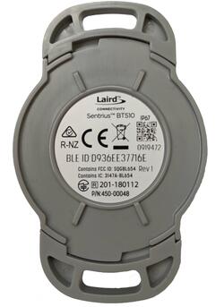
More information about the board can be found at the Sentrius BT510 website [1].
Hardware
Supported Features
The bt510 board supports the hardware features listed below.
- on-chip / on-board
- Feature integrated in the SoC / present on the board.
- 2 / 2
-
Number of instances that are enabled / disabled.
Click on the label to see the first instance of this feature in the board/SoC DTS files. -
vnd,foo -
Compatible string for the Devicetree binding matching the feature.
Click on the link to view the binding documentation.
bt510/nrf52840 target
On-target memory for this board target: 256 KiB of RAM, 1 MiB of Flash.
Type |
Location |
Description |
Compatible |
|---|---|---|---|
CPU |
on-chip |
ARM Cortex-M4F CPU1 |
|
ADC |
on-chip |
Nordic Semiconductor nRF family SAADC node1 |
|
ARM architecture |
on-chip |
Nordic UICR (User Information Configuration Registers)1 |
|
on-chip |
Nordic EGU (Event Generator Unit)6 |
||
on-chip |
Nordic nRF family ACL (Access Control List)1 |
||
on-chip |
Nordic nRF family MWU (Memory Watch Unit)1 |
||
Audio |
on-chip |
Nordic PDM (Pulse Density Modulation interface)1 |
|
Clock control |
on-chip |
Nordic nRF clock control node1 |
|
on-chip |
Nordic nRF high-frequency crystal oscillator (nRF52 series)1 |
||
Comparator |
on-chip |
Nordic nRF COMP (analog COMParator)1 |
|
Counter |
on-chip |
Nordic nRF timer node5 |
|
Cryptographic accelerator |
on-chip |
Nordic ECB (AES electronic codebook mode encryption)1 |
|
on-chip |
Nordic nRF family CCM (AES CCM mode encryption)1 |
||
on-chip |
ARM TrustZone CryptoCell 3101 |
||
Debug |
on-chip |
ARMv7 instrumentation trace macrocell1 |
|
Flash controller |
on-chip |
Nordic NVMC (Non-Volatile Memory Controller)1 |
|
on-chip |
Properties defining the interface for the Nordic QSPI peripheral1 |
||
GPIO & Headers |
on-chip |
NRF5 GPIOTE1 |
|
on-chip |
NRF5 GPIO2 |
||
I2C |
on-chip |
||
I2S |
on-chip |
Nordic I2S (Inter-IC sound interface)1 |
|
IEEE 802.15.4 |
on-chip |
Nordic nRF IEEE 802.15.4 node1 |
|
Input |
on-board |
Group of GPIO-bound input keys1 |
|
Interrupt controller |
on-chip |
ARMv7-M NVIC (Nested Vectored Interrupt Controller)1 |
|
LED |
on-board |
Group of GPIO-controlled LEDs1 |
|
Miscellaneous |
on-chip |
Nordic FICR (Factory Information Configuration Registers)1 |
|
on-chip |
Nordic nRF family PPI (Programmable Peripheral Interconnect)1 |
||
MTD |
on-chip |
Flash node1 |
|
on-board |
Fixed partitions of a flash (or other non-volatile storage) memory1 |
||
Networking |
on-chip |
Nordic nRF family RADIO peripheral1 |
|
on-chip |
Nordic nRF family NFCT (Near Field Communication Tag)1 |
||
Pin control |
on-chip |
Nordic nRF family Pin Controller1 |
|
Power management |
on-chip |
Nordic nRF power control node1 |
|
PWM |
on-chip |
nRF PWM4 |
|
on-chip |
nRFx S/W PWM1 |
||
Regulator |
on-chip |
Nordic nRF5X regulator (fixed stage of the core supply)1 |
|
on-chip |
Nordic nRF52X regulator (high voltage stage of the main supply)1 |
||
Retained memory |
on-chip |
Nordic GPREGRET (General Purpose Register Retention) device2 |
|
RNG |
on-chip |
Nordic nRF family RNG (Random Number Generator)1 |
|
RTC |
on-chip |
Nordic nRF RTC (Real-Time Counter)3 |
|
Sensors |
on-board |
STMicroelectronics LIS2DH12 3-axis accelerometer1 |
|
on-board |
Si7055 temperature sensor1 |
||
on-chip |
Nordic nRF family TEMP node1 |
||
on-chip |
Nordic nRF quadrature decoder (QDEC) node1 |
||
on-board |
SM351LT magnetoresistive sensor1 |
||
Serial controller |
on-chip |
||
SPI |
on-chip |
Nordic nRF family SPIM (SPI master with EasyDMA)4 |
|
SRAM |
on-chip |
Generic on-chip SRAM1 |
|
Timer |
on-chip |
ARMv7-M System Tick1 |
|
USB |
on-chip |
Nordic nRF52 USB device controller1 |
|
Watchdog |
on-chip |
Nordic nRF family WDT (Watchdog Timer)1 |
Connections and IOs
LED
Two LEDs are visible through the BT510 housing lid.
LED_1A (green) = P0.22
LED_1B (red) = P0.20
Magnetoresistive sensor
The BT510 incorporates a Honeywell SM351LT magnetoresistive sensor. Refer to the Honeywell SM351LT datasheet [7] for further details.
MAG = P1.14
Accelerometer
The BT510 incorporates an I2C ST Microelectronics LIS2DH accelerometer. Refer to the ST Microelectronics LIS2DH datasheet [6] for further details.
SDA = P0.26
SCL = P0.27
INT_1 = P1.05
INT_2 = P1.12
Temperature Sensor
The BT510 incorporates an I2C Silabs SI7055 temperature sensor. Refer to the Silabs 7055 datasheet [5] for further details.
SDA = P0.26
SCL = P0.27
Programming and Debugging
The bt510 board supports the runners and associated west commands listed below.
| flash | debug | rtt | attach | reset | debugserver | |
|---|---|---|---|---|---|---|
| jlink | ✅ | ✅ | ✅ | ✅ | ✅ | ✅ |
| nrfjprog | ✅ | |||||
| nrfutil | ✅ | |||||
| pyocd | ✅ (default) | ✅ (default) | ✅ | ✅ | ✅ |
Applications for the bt510 board configuration can be built, flashed, and
debugged in the usual way. See Building an Application and
Run an Application for more details on building and running.
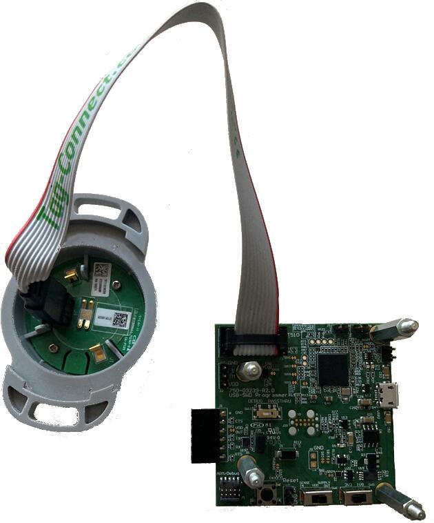
The BT510 features a TagConnect 10 way socket for connection of a programmer/debugger, refer to TagConnect TC2050 product page [2] for details of an appropriate TagConnect cable.
A non-standard layout is used to include access to the sensor debug UART.
Pin No. |
Name |
Description |
|---|---|---|
1 |
Vcc |
Power Supply, 3.3V |
2 |
SWDIO |
SWD Data |
3 |
RXD |
Debug UART RX Data |
4 |
SWDCLK |
SWD Clock |
5 |
TM |
Spare GPIO |
6 |
SWO |
SWD Output |
7 |
N/C |
Not Connected |
8 |
TXD |
Debug UART TX Data |
9 |
GND |
Ground |
10 |
RESET |
Reset, Active Low |
Connectivity to the programmer/debugger must be modified to match the pinout shown above.
Ezurio provide the USB-SWD programming board (750-03239) that supports this connector layout, refer to the USB SWD Programmer product page [3] .
Flashing
To connect the BT510 board for programming or debugging using the USB-SWD programming board, on the programming board set SW6 to the supply out position and SW5 to the 3V3 position, ensure there is a jumper on J35 and that SW1 is in the debug position, then connect the BT510 to the board using the Tag-Connect cable via J3:
Then build and flash applications as usual (see Building an Application and Run an Application for more details). For example, to flash:
$ ninja flash
Here is an example for the Hello World application.
First, run your favorite terminal program to listen for output.
NOTE: On the BT510, the UART lines are at TTL levels and must be passed through an appropriate line driver circuit for translation to RS232 levels. Refer to the MAX3232 datasheet [4] for a suitable driver IC. The USB-SWD programming board has an in-built UART connected to the BT510 acting as a USB CDC port, on Linux and Windows 10 this driver should be installed automatically, for Windows 7, the MBED driver is required to use the serial port - see the MBED Serial Driver [8] link for details and how to install the driver.
$ minicom -D <tty_device> -b 115200
Replace <tty_device> with the port where the bt510 can be found. For example, under Linux, /dev/ttyACM0.
Then build and flash the application in the usual way.
# From the root of the zephyr repository
west build -b bt510 samples/hello_world
west flash
Note that an external debugger is required to perform application flashing.
Debugging
The bt510 board does not have an on-board J-Link debug IC
as some nRF5x development boards, however, instructions from the
Nordic nRF5x Segger J-Link page also apply to this board, with the additional step
of connecting an external debugger. The USB-SWD programmer board has a CMSIS debugger
compatible interface and debugging can be performed using pyocd, openocd or any other
applications that support the CMSIS interface.
Testing Bluetooth on the BT510
Many of the Bluetooth examples will work on the BT510. Try them out: