ESP32-S3-EYE
Overview
The ESP32-S3-EYE is a small-sized AI development board produced by Espressif and based on the ESP32-S3 SoC. It features a 2-Megapixel camera, an LCD display, and a microphone, which are used for image recognition and audio processing. ESP32-S3-EYE offers plenty of storage, with an 8 MB Octal PSRAM and a 8 MB flash.
Hardware
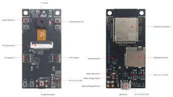
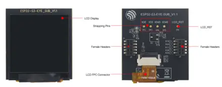
The ESP32-S3-EYE board consists of two parts: the main board (ESP32-S3-EYE-MB) that integrates the ESP32-S3-WROOM-1 module, camera, SD card slot, digital microphone, USB port, and function buttons; and the sub board (ESP32-S3-EYE-SUB) that contains an LCD display. The main board and sub board are connected through pin headers.
ESP32-S3 Features
ESP32-S3 is a low-power MCU-based system on a chip (SoC) with integrated 2.4 GHz Wi-Fi and Bluetooth® Low Energy (Bluetooth LE). It consists of high-performance dual-core microprocessor (Xtensa® 32-bit LX7), a low power coprocessor, a Wi-Fi baseband, a Bluetooth LE baseband, RF module, and numerous peripherals.
ESP32-S3 SoC includes the following features:
Dual core 32-bit Xtensa Microprocessor (Tensilica LX7), running up to 240MHz
Additional vector instructions support for AI acceleration
512KB of SRAM
384KB of ROM
Wi-Fi 802.11b/g/n
Bluetooth LE 5.0 with long-range support and up to 2Mbps data rate
Digital interfaces:
45 programmable GPIOs
4x SPI
1x LCD interface (8-bit ~16-bit parallel RGB, I8080 and MOTO6800), supporting conversion between RGB565, YUV422, YUV420 and YUV411
1x DVP 8-bit ~16-bit camera interface
3x UART
2x I2C
2x I2S
1x RMT (TX/RX)
1x pulse counter
LED PWM controller, up to 8 channels
1x full-speed USB OTG
1x USB Serial/JTAG controller
2x MCPWM
1x SDIO host controller with 2 slots
General DMA controller (GDMA), with 5 transmit channels and 5 receive channels
1x TWAI® controller, compatible with ISO 11898-1 (CAN Specification 2.0)
Addressable RGB LED, driven by GPIO38.
Analog interfaces:
2x 12-bit SAR ADCs, up to 20 channels
1x temperature sensor
14x touch sensing IOs
Timers:
4x 54-bit general-purpose timers
1x 52-bit system timer
3x watchdog timers
Low Power:
Power Management Unit with five power modes
Ultra-Low-Power (ULP) coprocessors: ULP-RISC-V and ULP-FSM
Security:
Secure boot
Flash encryption
4-Kbit OTP, up to 1792 bits for users
Cryptographic hardware acceleration: (AES-128/256, Hash, RSA, RNG, HMAC, Digital signature)
Asymmetric Multiprocessing (AMP)
Boards featuring the ESP32 and ESP32-S3 SoC allows 2 different applications to be executed. Due to its dual-core architecture, each core can be enabled to execute customized tasks in stand-alone mode and/or exchanging data over OpenAMP framework. See Inter-Processor Communication (IPC) folder as code reference.
Note
AMP and serial output support
In the current Zephyr ESP32 implementation, access to Zephyr-managed serial
drivers (such as printk(), logging, or the console UART) is not yet
implemented for applications running on the APPCPU. As a result, serial
output APIs provided by Zephyr are only available on the PROCPU.
As a mitigation, applications running on the APPCPU may use ESP32 ROM
functions such as ets_printf() to emit diagnostic or debug output.
For more information, check the ESP32-S3 Datasheet [1] or the ESP32-S3 Technical Reference Manual [2].
Supported Features
The esp32s3_eye board supports the hardware features listed below.
- on-chip / on-board
- Feature integrated in the SoC / present on the board.
- 2 / 2
-
Number of instances that are enabled / disabled.
Click on the label to see the first instance of this feature in the board/SoC DTS files. -
vnd,foo -
Compatible string for the Devicetree binding matching the feature.
Click on the link to view the binding documentation.
esp32s3_eye/esp32s3/appcpu target
On-target memory for this board target: 416 KiB of RAM, 4 MiB of Flash.
Type |
Location |
Description |
Compatible |
|---|---|---|---|
CPU |
on-chip |
Espressif Xtensa LX7 CPU2 |
|
ADC |
on-chip |
ESP32 ADC2 |
|
Bluetooth |
on-chip |
Bluetooth HCI for Espressif ESP321 |
|
CAN |
on-chip |
ESP32 Two-Wire Automotive Interface (TWAI)1 |
|
Clock control |
on-chip |
ESP32 Clock (Power & Clock Controller Module) Module1 |
|
Counter |
on-chip |
ESP32 Counter Driver based on RTC Main Timer1 |
|
on-chip |
|||
on-chip |
ESP32 counters4 |
||
Cryptographic accelerator |
on-chip |
Espressif ESP32 SHA Hardware Accelerator1 |
|
on-chip |
Espressif ESP32 family AES Hardware Accelerator1 |
||
DMA |
on-chip |
ESP32 GDMA (General Direct Memory Access)1 |
|
Flash controller |
on-chip |
ESP32 flash controller1 |
|
GPIO & Headers |
on-chip |
ESP32 GPIO controller2 |
|
I2C |
on-chip |
ESP32 I2C2 |
|
I2S |
on-chip |
ESP32 I2S2 |
|
Input |
on-chip |
ESP32 touch sensor input1 |
|
Interrupt controller |
on-chip |
ESP32 Interrupt controller1 |
|
IPM |
on-chip |
ESP32 soft inter processor message1 |
|
Mailbox |
on-chip |
ESP32 soft mailbox1 |
|
Memory controller |
on-chip |
ESP32 pseudo-static RAM controller1 |
|
MIPI-DBI |
on-chip |
ESP32 LCD-CAM display interface1 |
|
Miscellaneous |
on-chip |
ESP32 LCD-CAM controller1 |
|
MTD |
on-chip |
Flash node1 |
|
Pin control |
on-chip |
ESP32 pin controller1 |
|
PWM |
on-chip |
ESP32 LED Control (LEDC)1 |
|
on-chip |
ESP32 Motor Control Pulse Width Modulator (MCPWM)2 |
||
RNG |
on-chip |
ESP32 TRNG (True Random Number Generator)1 |
|
SDHC |
on-chip |
ESP32 SDHC controller1 |
|
on-chip |
ESP32 SDHC controller slot2 |
||
Sensors |
on-chip |
ESP32 internal temperature sensor1 |
|
on-chip |
ESP32 Pulse Counter (PCNT)1 |
||
Serial controller |
on-chip |
ESP32 UART3 |
|
on-chip |
ESP32 UART1 |
||
SPI |
on-chip |
ESP32 SPI controller2 |
|
SRAM |
on-chip |
Generic on-chip SRAM2 |
|
USB |
on-chip |
ESP32 USB-OTG (DWC2 compatible controller)1 |
|
Video |
on-chip |
ESP32 LCD-CAM camera interface1 |
|
Watchdog |
on-chip |
ESP32 XT Watchdog Timer1 |
|
on-chip |
ESP32 watchdog2 |
||
Wi-Fi |
on-chip |
ESP32 SoC Wi-Fi1 |
esp32s3_eye/esp32s3/procpu target
On-target memory for this board target: 416 KiB of RAM, 8 MiB of Flash.
Type |
Location |
Description |
Compatible |
|---|---|---|---|
CPU |
on-chip |
Espressif Xtensa LX7 CPU2 |
|
ADC |
on-chip |
||
Bluetooth |
on-chip |
Bluetooth HCI for Espressif ESP321 |
|
CAN |
on-chip |
ESP32 Two-Wire Automotive Interface (TWAI)1 |
|
Clock control |
on-chip |
ESP32 Clock (Power & Clock Controller Module) Module1 |
|
Counter |
on-chip |
ESP32 Counter Driver based on RTC Main Timer1 |
|
on-chip |
|||
on-chip |
ESP32 counters4 |
||
Cryptographic accelerator |
on-chip |
Espressif ESP32 SHA Hardware Accelerator1 |
|
on-chip |
Espressif ESP32 family AES Hardware Accelerator1 |
||
Display |
on-board |
Sitronix ST7789V display controller1 |
|
DMA |
on-chip |
ESP32 GDMA (General Direct Memory Access)1 |
|
Flash controller |
on-chip |
ESP32 flash controller1 |
|
GPIO & Headers |
on-chip |
ESP32 GPIO controller2 |
|
I2C |
on-chip |
||
I2S |
on-chip |
ESP32 I2S2 |
|
Input |
on-chip |
ESP32 touch sensor input1 |
|
on-board |
Group of GPIO-bound input keys1 |
||
on-board |
Input driver for ADC attached resistor ladder buttons1 |
||
Interrupt controller |
on-chip |
ESP32 Interrupt controller1 |
|
IPM |
on-chip |
ESP32 soft inter processor message1 |
|
LED |
on-board |
Group of GPIO-controlled LEDs1 |
|
Mailbox |
on-chip |
ESP32 soft mailbox1 |
|
Memory controller |
on-chip |
ESP32 pseudo-static RAM controller1 |
|
MIPI-DBI |
on-chip |
ESP32 LCD-CAM display interface1 |
|
Miscellaneous |
on-chip |
ESP32 LCD-CAM controller1 |
|
MTD |
on-chip |
Flash node1 |
|
Pin control |
on-chip |
ESP32 pin controller1 |
|
PWM |
on-chip |
ESP32 LED Control (LEDC)1 |
|
on-chip |
ESP32 Motor Control Pulse Width Modulator (MCPWM)2 |
||
RNG |
on-chip |
ESP32 TRNG (True Random Number Generator)1 |
|
SDHC |
on-chip |
ESP32 SDHC controller1 |
|
on-chip |
|||
Sensors |
on-chip |
ESP32 internal temperature sensor1 |
|
on-chip |
ESP32 Pulse Counter (PCNT)1 |
||
Serial controller |
on-chip |
ESP32 UART3 |
|
on-chip |
ESP32 UART1 |
||
SPI |
on-chip |
||
SRAM |
on-chip |
Generic on-chip SRAM2 |
|
USB |
on-chip |
ESP32 USB-OTG (DWC2 compatible controller)1 |
|
Video |
on-board |
OV2640 CMOS video sensor1 |
|
on-chip |
ESP32 LCD-CAM camera interface1 |
||
Watchdog |
on-chip |
ESP32 XT Watchdog Timer1 |
|
on-chip |
|||
Wi-Fi |
on-chip |
ESP32 SoC Wi-Fi1 |
Block Diagram
The block diagram below presents main components of the ESP32-S3-EYE-MB main board (on the left) and the ESP32-S3-EYE-SUB sub board (on the right), as well as the interconnections between components.
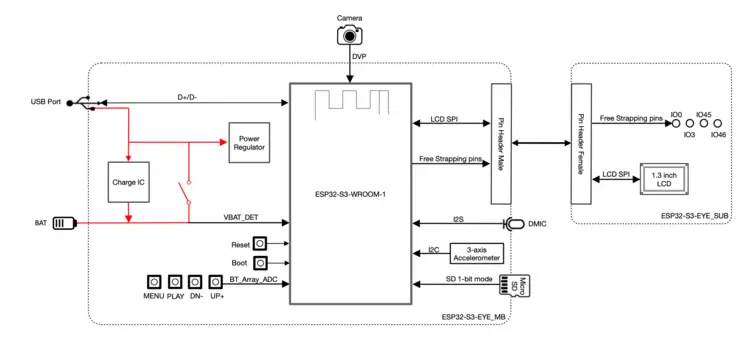
Components on the ESP32-S3-EYE-MB Main Board
Components on the ESP32-S3-EYE-SUB Sub Board
System Requirements
Binary Blobs
Espressif HAL requires RF binary blobs in order work. Run the command below to retrieve those files.
west blobs fetch hal_espressif
Note
It is recommended running the command above after west update.
Programming and Debugging
The esp32s3_eye board supports the runners and associated west commands listed below.
| flash | debug | rtt | attach | debugserver | |
|---|---|---|---|---|---|
| esp32 | ✅ (default) | ||||
| openocd | ✅ | ✅ (default) | ✅ | ✅ | ✅ |
Simple Boot
The board could be loaded using the single binary image, without 2nd stage bootloader. It is the default option when building the application without additional configuration.
Note
Simple boot does not provide any security features nor OTA updates.
MCUboot Bootloader
User may choose to use MCUboot bootloader instead. In that case the bootloader must be built (and flashed) at least once.
There are two options to be used when building an application:
Sysbuild
Manual build
Note
User can select the MCUboot bootloader by adding the following line to the board default configuration file.
CONFIG_BOOTLOADER_MCUBOOT=y
Sysbuild
The sysbuild makes possible to build and flash all necessary images needed to bootstrap the board with the ESP32 SoC.
To build the sample application using sysbuild use the command:
west build -b <board> --sysbuild samples/hello_world
By default, the ESP32 sysbuild creates bootloader (MCUboot) and application images. But it can be configured to create other kind of images.
Build directory structure created by sysbuild is different from traditional Zephyr build. Output is structured by the domain subdirectories:
build/
├── hello_world
│   └── zephyr
│       ├── zephyr.elf
│       └── zephyr.bin
├── mcuboot
│    └── zephyr
│       ├── zephyr.elf
│       └── zephyr.bin
└── domains.yaml
Note
With --sysbuild option the bootloader will be re-build and re-flash
every time the pristine build is used.
For more information about the system build please read the Sysbuild (System build) documentation.
Manual Build
During the development cycle, it is intended to build & flash as quickly possible. For that reason, images can be built one at a time using traditional build.
The instructions following are relevant for both manual build and sysbuild. The only difference is the structure of the build directory.
Note
Remember that bootloader (MCUboot) needs to be flash at least once.
Build and flash applications as usual (see Building an Application and Run an Application for more details).
# From the root of the zephyr repository
west build -b <board> samples/hello_world
The usual flash target will work with the board configuration.
Here is an example for the Hello World
application.
# From the root of the zephyr repository
west build -b <board> samples/hello_world
west flash
Note
On targets that expose the built-in USB Serial/JTAG controller, the chip can
stay in download mode after west flash and will not boot the new image
until it is power cycled. If that happens, flash with a watchdog reset so the
chip restarts on its own:
west flash --reset-type watchdog-reset
Faster Flashing
To speed up the development cycle, --esp-skip-flashed skips writing the image
when the binary already in flash matches the one being flashed, verified with an
MD5 check on the device:
west flash --esp-skip-flashed
For an even faster reflash, --esp-diff writes only the regions that differ
from the previously flashed image. It compares against a locally cached copy
rather than reading the device, so use it only when the flash was not modified
by another tool, board, or manual write since the last west flash:
west flash --esp-diff
Progress output can be suppressed for cleaner logs, which is useful in CI:
west flash --esp-no-progress
Open the serial monitor using the following command:
west espressif monitor
After the board has automatically reset and booted, you should see the following message in the monitor:
***** Booting Zephyr OS vx.x.x-xxx-gxxxxxxxxxxxx *****
Hello World! <board>
Board variants using Snippets
ESP32 boards can be assembled with different modules using multiple combinations of SPI flash sizes, PSRAM sizes and PSRAM modes.
The snippets under snippets/espressif provide a modular way to apply these variations at build time without duplicating board definitions.
The following snippet-based variants are supported:
Snippet name |
Description |
|---|---|
Flash memory size |
|
|
Board with 4MB of flash |
|
Board with 8MB of flash |
|
Board with 16MB of flash |
|
Board with 32MB of flash |
|
Board with 64MB of flash |
|
Board with 128MB of flash |
PSRAM memory size |
|
|
Board with 2MB of PSRAM |
|
Board with 4MB of PSRAM |
|
Board with 8MB of PSRAM |
PSRAM utilization |
|
|
Relocate flash to PSRAM |
|
Wi-Fi buffers in PSRAM |
To apply a board variant, use the -S flag with west build:
west build -b <board> -S espressif-flash-32M -S espressif-psram-4M samples/hello_world
Note
These snippets are only applicable to boards with compatible hardware support for the selected flash/PSRAM configuration.
If no FLASH snippet is used, the board default flash size will be used.
If no PSRAM snippet is used, the board default psram size will be used.
Debugging
OpenOCD Debugging
Espressif chips require a custom OpenOCD build with ESP32-specific patches. Download the latest release from OpenOCD for ESP32 [3].
For detailed JTAG setup instructions, see JTAG debugging for ESP32 [5].
Zephyr Thread Awareness
OpenOCD supports Zephyr RTOS thread awareness, allowing GDB to:
List all threads with
info threadsDisplay thread names, priorities, and states
Switch between thread contexts
Show backtraces for any thread
Requirements:
OpenOCD ESP32 v0.12.0-esp32-20251215 [4] or later
Build with
CONFIG_DEBUG_THREAD_INFO=y
Example:
# From the root of the zephyr repository
west build -b <board> samples/hello_world -- -DCONFIG_DEBUG_THREAD_INFO=y -DOPENOCD=<path/to/bin/openocd> -DOPENOCD_DEFAULT_PATH=<path/to/openocd/share/openocd/scripts>
west debug
Using a Custom OpenOCD
The Zephyr SDK includes a bundled OpenOCD, but it may not have ESP32 support. To use the Espressif OpenOCD, specify the path when building:
# From the root of the zephyr repository
west build -b <board> samples/hello_world -- -DOPENOCD=/path/to/openocd -DOPENOCD_DEFAULT_PATH=/path/to/openocd/scripts
west debug